ILDA Breakout Board
Version 1-2 Breakout Board
Version 3 Breakout Board
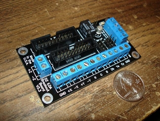
Version 1-2 Breakout Board
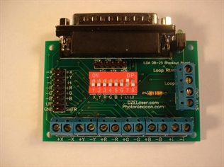
The Version 1 and Version 2 Breakout Boards are identical except for the additional pins for Deep Blue, Cyan and Yellow.Screw Terminals
- +X +Y.. X or Y axis scanner, +side
- -X -Y.. This is not GND or common, this is the -X/-Y in differential
- +RGB.. Color lines
- -RGB.. This is not GND or common, this is the -RGB in differential
- +i.. This is intensity and should be used if you have single color
- -i.. This is not GND or common, this is the -i in differential
- SHTR.. Shutter singal from your DAC
- GND.. Pin 25 on the ILDA cable
- Loop.. This is where you want to apply voltage for your interlock loop, ideally, you will want to send the loop signal thru all items in your projector (cover interlock, etc.) then attach it to "loop" on the breakout board . I recommend the loop to be either +5 or +12VDC and is not suppose to exceed 160mA. With an ILDA cable attached to your DAC, the loop signal should return on "Loop Rtrn". If this is true, the LED will be lit. Note, the LED will draw about 12mA of current on the Loop. The LED itself, isn't meant to be used as an emission indicator. All it does is tell you that the loop signal has returned to the ILDA Breakout board .
- Loop Rtrn.. Described above
The pin header is used to pass the signals thru to a second projector.Switch Block
- XY.. These affect the -X and -Y outputs, turning these on connects -X and -Y to GND. Most scanners now have differential, so you really shouldn't need this. Also note, that some DAC's may not survive having their -X and -Y outputs grounded! It will not hurt the QM2K to have -X and -Y grounded. Use caution when using #1 and #2 on the switch block.
- RGB.. This connects -RGB to GND for single ended lasers. On some older QM2Ks, this also increases the output of +RGB from 2.5V to 5V
- i.. This connects the -i (intensity) to GND for single color projectors
- L1 & L2.. This sets up how the Loop works, IF, the breakout board is connected only to a DAC and you have no secondary projector attached to the pin header, you will want to have L1 set to ON. IF, you are passing the signal thru to another projector, AND you want the interlock loop to be fed to the secondary projector, set L1 to OFF and L2 to ON. With L1 OFF and L2 ON, the loop signal gets sent thru the pin header to a secondary projector, then returns to the ILDA breakout board and gets send to the DAC, then returns from the DAC to the "Loop Rtrn" line.
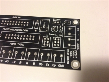
For the Version 3 Breakout Board, the DB-25 connector was removed from the board to allow for easier mounting inside a projector. The breakout board will include a ribbon cable from the DB-25 that attaches to the new board. The 2nd ribbon cable is for an optional pass-thru. The screw terminals function similar to the v1 and v2 breakout boards except that the "-" color lines have been removed.
The next item is the interlock lock. This 3rd generation breakout board has a completely redesigned loop circuit. Since every projector should have it's own interlock loop, inter-mixing projectors together with passthru cables create problems with these independent loops. So, the breakout board now features an active loop circuit. The passthru cable interlock loop is competely isolated from the ILDA in cable. If the ILDA in loop comes disconnected from the DAC, the passthru cable interlock loop will also go open and interupt the 2nd projector. This is an optional feature to take advantage of, if you do not wish for the passthru interlock loop to be dependent on projector 1's interlock loop being satisfied, then you can attach a jumper to the "bypass" pin header. This will make projector 1 appear as a DAC to projector 2 since projector 1 cannot interupt the passthru cable interlock loop. Have I lost you yet?! Ok, in order to make this work correctly, your interlock circuitry in your projector must have a common connection to ground, including the breakout board's GND connection (which is basically ILDA pin 25). You then run the + side of your loop thru what ever makes up your loop circuit, cover switches, EPO switches, etc. Then, that + voltage needs to connect to the "L" screw terminal on the breakout board. This will send the +V out on ILDA pin 4 to your DAC, which will return the +V back on pin 17 which is tied to the "LR" screw terminal. If, +V is present on the "LR" screw terminal, this will feed a small LED on the board to show that the interlock loop is satisfied, it will also feed the base of a transistor, which will close a relay to short ILDA pins 4 and 17 together on the passthru cable. So, if properly working and the bypass does not have a jumper, disconnection from your DAC will open both interlock loops.
By default, you will receive a v3 breakout board with jumpers attached to the "invert" pin headers. By swapping the jumpers you can invert the projectors output image. You can also remove the jumpers and wire a DPDT switch to the side of your projector to be able to quickly invert the projector image orientation.
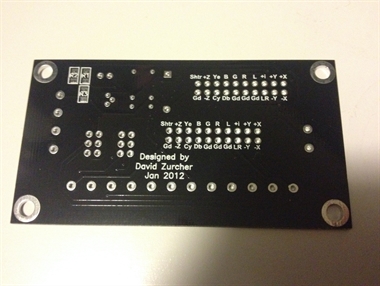
Version 3 Breakout Board
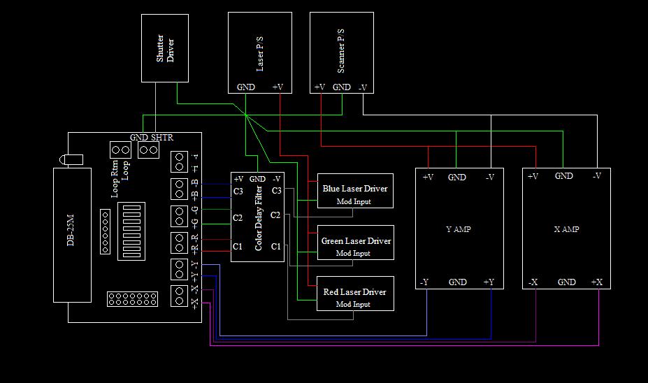
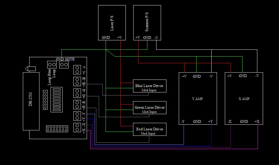
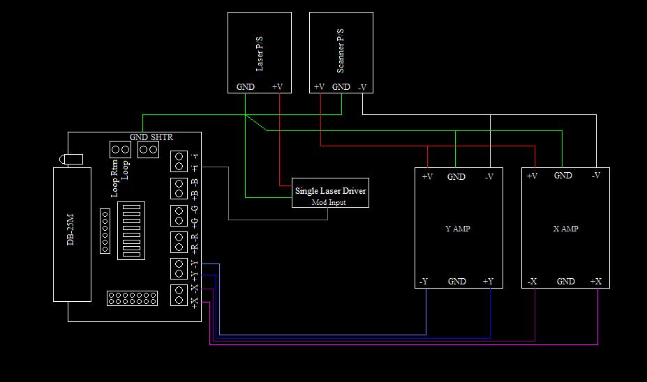
I created the following images for the orignal V1 and V2 breakout boards however the principal is still the same for the V3 breakout board. Ultimately, the absolute best guide for projector wiring was created by Bill Benner and can be found here.