
Z-5 Modifications
The Z-5 analog console is a complex system of circuitry designed to create stunning and colorful abstract images. Opening the Z-5 will reveal a very intimidating and complex network of wiring that gives life to the console. On this page, I will share several modifications and improvements that I have explored to improve the product by either adding a new function or changing the way a current function works.
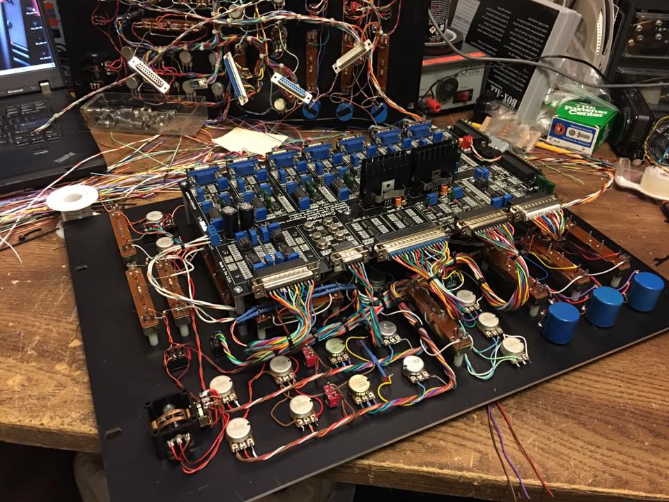
I am a huge advocate of DIY and I encourage users to freely make modifications to a Z-5. Below I will discuss by section what modification I have made, some made significant improvements others not so much. I hope that you will find the information here valuable in making your own modifications. Of course, if you would prefer, your Z-5 can be returned to have these modifications implemented.
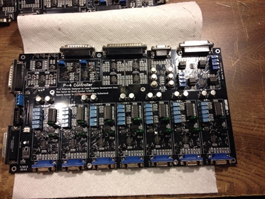
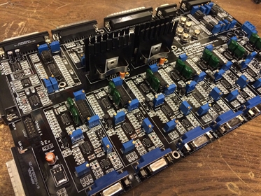
There are two versions of the Z-5 console, v2 and v4. v2 was the first run of circuit boards that required a few modifications during assembly to make them work correctly. There are also two added circuit boards that reside under the main circuit board for added functionality. The v4 circuit board incorporated these fixes and improvements. The v4 circuit board incorporates the following changes compared to the v2 board:
- Power Regulators - These was moved from the lower 2U panel to the main PCB with Aavid heat sinks. This change allows the use of switching power supplies on the 2U panel to support 90-250VAC 50-60Hz AC input. Having the power regulators located on the main pcb also helps to reduce noise thruout the circuit board. The downside here is that the Z-5 console now requires a small fan to keep the regulators cool.
- Ground Plane - The ground plane on the v4 board was greatly improved to help reduce noise thruout the circuit board.
- Audio - Filtering is now performed on the main pcb instead of the lower 2U panel. The audio in has a low pass filter to prevent high frequency audio from damaging your laser scanners. The audio out has DC blocking caps to prevent the Z-5 from damaging your speakers.
- External VCA - This VCA was added to manipulate an external image from a DAC or another analog console separate from the internal image VCA. On the v2 console, this is a circuit board that resides under the main pcb. On the v4 console, this circuit has been added to the main pcb.
- Trace Cleanup - The v2 circuit board was auto routed and contained 24,635 traces and 1,170 vias. The v4 circuit board was rerouted by hand and contains 13,757 traces and 477 vias. This also includes the new VCA and audio processing circuit! This significant reduction in traces and vias help to reduce noise thruout the Z-5.
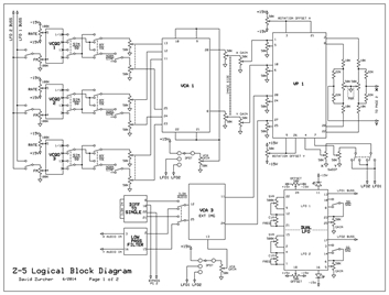
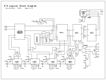
So let's take a look at how a signal flows thru the Z-5 console. Below is the logical block diagram. Click on the images below to take a closer look. The signal flows from the left to the right, so a signal from VCQO1 would pass thru the following circuits in order: VCA1, VP1, PAN circuit, Rotation Matrix, VCA2, VP2 and finally the single to diff circuit.
Modification Topics: