
Wave-USB Pro
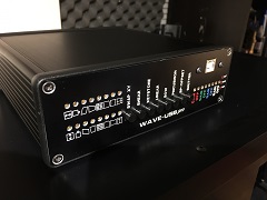
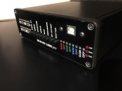
I am proud to present the Wave-USB Pro! The orignal Wave-USB was designed as a simple way to record laser signals from my analog console, the Z-5. Unfortunately, one of the main components of the Wave-USB was discontinued by the manufacturer. The only way to keep this product alive was to completely redesign it from the ground up!
PLEASE READ
I completely enjoy making products like this but please understand that this is just a hobby for me. When I design a product, my main goal isn't to keep the price low. I want something that's reliable and I try to use, what I believe is, the best quality components. As an example, there are 24 externally accessible trim potentiometers and 8 internal. They are all manufactured by Bourns and represent $121.76 of the total cost of a Wave-USB Pro. When I started this project, I had hoped that the Wave-USB Pro would be around the same price as the previous Wave-USB. I was a good bit off...
Please understand, no one needs a Wave-USB Pro, this is a very specialized and grossly overpriced device! Fact is, if you have laser show content in wave format, you can build a very capable, modified, 7.1 channel sound card DAC to do the same job, and for around $50. If you want to record a laser show as a multi-channel wave file, you could purchase an old Alesis ADAT and a MiniDSP USBStreamer for around $200. The point is, there are other ways to go down the path of wave laser shows other than the Wave-USB Pro.
If, after all that, you are still interested in the Wave-USB Pro then please continue below!
PLEASE READ
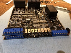
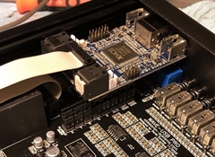
The Wave-USB Pro is built around MiniDSP's MCHStreamer. The MCHStreamer provides the USB interface to a host which can be a PC, MAC or iPhone. The interface between the ADC/DAC and the MCHStreamer supports up to 32bit at 384KHz sample rate. The ADC/DAC within the Wave-USB Pro are premium Asahi Kasei components, featuring the Velvet Sound architecture.

The Wave-USB Pro also features Geometric Correction! This allows for basic correction of a projected image from a laser projector. The trimmer potentiometers, accessible from the front of the Wave-USB Pro, include image size, image offset, skew, keystone, linear, bow, pincushion and bow/pincushion offset. Many of these functions can be enabled or disabled with push-buttons on the front of the Wave-USB Pro. Additional push-buttons allow for swapping the X/Y signal and manually opening a projector shutter. It is also possible to invert the X/Y signal by turning the X/Y image size trimmers fully counter-clockwise
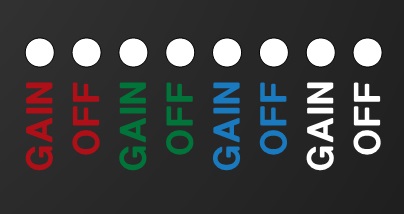
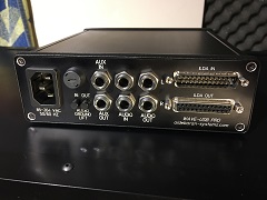
The RGB gain and offset trimmers allow adjustment of the playback signals only. There is also an auxillary channel, defined by the ILDA standard as audio channel 6. This channel can be routed to any of the additional ILDA color channels, shutter signal or to the 1/4" jack on the rear of the Wave-USB Pro. This channel is typically used for recording SMPTE time code. The additional gain/offset trimmers allow for the adjustment of this auxillary channel. The routing of the auxillary channel for recording and playback is configured thru a series of jumpers on the inside of the Wave-USB Pro.
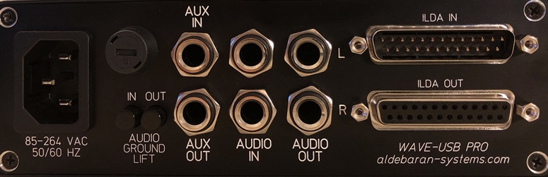
The Wave-USB Pro uses a standard C14 AC power receptical and accepts 85 to 264VAC. The audio in/out, as well as the AUX in/out, are 1/4" fully balanced. Both audio in and out can accomodate a TS (unbalanced) 1/4" audio cable or a TRS (balanced) 1/4" audio cable. The sleeve on audio in/out can be connected to or isolated from ground separately via adjacent push-button switches.
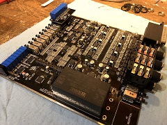
The ILDA IN connector is a standard D-Sub 25 with fully balanced (differential) inputs on all channels, including color.
The ILDA OUT connector is *nearly* standard. X/Y is fully balanced (differential) however, the color channels are not. There are very few, if any, laser projectors that support true differential color input.
The price for a completed Wave-USB Pro is $1,295 plus shipping
Availability: limited
Ordering: Please send me an email if you're interested in ordering a Wave-USB Pro. I order the parts to assemble a Wave-USB Pro when an order is placed and payment has been received. A rough estimate on delivery is 4-6 weeks.
Availability: limited
Ordering: Please send me an email if you're interested in ordering a Wave-USB Pro. I order the parts to assemble a Wave-USB Pro when an order is placed and payment has been received. A rough estimate on delivery is 4-6 weeks.
The Audio Polarity Inversion Anomaly
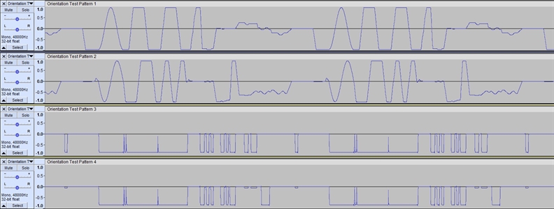
In the audio world, you are generally dealing with an AC coupled, fast moving bi-polar signal. When recording laser show signals, it's vitally important to be able to record a steady, DC coupled signal. When you send +5V to an X/Y or RGB channel, you expect +5V on the playback side as well, and generally this does occur. Interestingly though, many DAW's show what appears to be an inverted signal. This issue is very noticeable on recorded color channels. As shown above, the third and fourth channel represent Red and Green and appear to go from the center line down. It is less apparent on channel 1 and 2 since this represents X/Y data however, it is indeed inverted as well.
This is an interesting anomaly that appears to have existed in the audio world for a very long time. I have created a couple ways that the Wave-USB Pro can mitigate this issue.
The trimmers that control X/Y image size and RGB+Aux gains are unique. These are all 25 turn trim potentiometers. When turned fully clockwize, the signal output is of normal polarity. When turned fully counter-clockwise, the signal is inverted. The center of travel of the trimmer is zero output. For the color channels, the offset trimmer will always add +V to the signal even if it's inverted.
A more permanent way to set the Wave-USB Pro to invert the playback signal is with a series of jumper settings. There are also jumpers for inverting the record signals as well.
Confused yet?! I put together a quick video showing the versatility of the Wave-USB Pro in handling this issue.
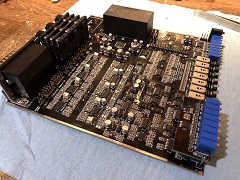
Jumper Settings

The above jumper settings will invert the playback channels. They are in pairs and must both be installed on each jumper set. Removing the two jumpers, reinstalling them turned 90 degrees will invert the individual channel.
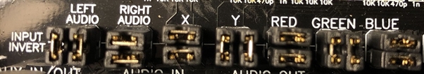
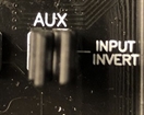
The input invert jumpers function the same way as the playback invert jumpers. Simply remove, turn 90 degrees and reinstall.
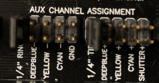
The above Aux channel assignment jumpers assign channel 6 to a particular input. These need to be set in pairs. If you want channel 6 to record a yellow color signal, then "YELLOW +" and "YELLOW -" need to be selected. By default, 1/4" Tip and Ring are set.
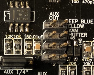
These jumpers affect Aux channel 6 playback assignment. The jumper at the lower left is a 3 pin jumper and will send the signal either to the 1/4" connector or to the jumpers in the middle. Starting from the top row, the signal can route to Deep Blue, Yellow, Cyan or the Shutter. By default, the signal will be set to the 1/4" connector.
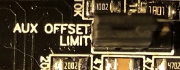
The Aux Offset Limit is a 3 pin jumper. This affects the offset trim potentiometer on the front of the Wave-USB Pro. When set one way, the offset trimmer can apply only a positive offset voltage to the signal. When set the other way, the offset trimmer can provide a positive or negative offset to the Aux signal. By default, this jumper will be set to only apply a positive voltage.
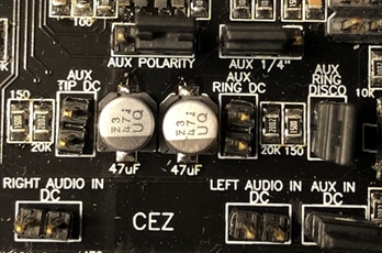
In the above pic, the lower three jumpers affect the recording channels of Aux and L/R Audio. With a jumper installed, these channels will be capable of recording a DC signal. Jumpers removed and they are AC coupled. By default, the audio channels are AC coupled and the Aux channel is DC coupled.
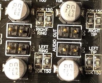
The jumpers closer to the top of the pic affect the playback Aux channel. Top right, routes the Aux out channel either to the 1/4" connector or to a separate jumper block for additional channel assignments. The Aux out channel can be AC or DC coupled with the jumpers in the middle. These need to be installed in pairs and by default the channel is AC coupled. The top left jumper has been renamed to Aux Clamp. With the Aux Clamp jumper set to the left two pins, the output of this channel will be limited to 0 to +5V. With the jumper on the right two pins, the channel can swing from -5V to +5V. By default, the channel is limited to 0 to +5V.
The jumpers closer to the top of the pic affect the playback Aux channel. Top right, routes the Aux out channel either to the 1/4" connector or to a separate jumper block for additional channel assignments. The Aux out channel can be AC or DC coupled with the jumpers in the middle. These need to be installed in pairs and by default the channel is AC coupled. The top left jumper has been renamed to Aux Clamp. With the Aux Clamp jumper set to the left two pins, the output of this channel will be limited to 0 to +5V. With the jumper on the right two pins, the channel can swing from -5V to +5V. By default, the channel is limited to 0 to +5V.
The above jumpers affect playback audio. With jumpers installed, the audio channels (7&8) are DC coupled. When removed, these channels are AC coupled. The jumpers need to be installed in pairs. The top two jumpers affect the right channel and the bottom two affect the left channel. By default, these jumpers will not be installed.
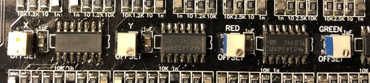
In the center of the board there are a total of 8 of these micro trimmers. These affect the recording signal zero offset. With no signal attached to the Wave-USB Pro, viewing the VU meters in a DAW, the idle signal should be set as low as possible. By making changes to input AC or DC coupling, it may be necessary to make slight adjustments to these trimmers.
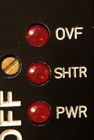
On the front of the Wave-USB Pro, there are 3 LED indicators. The lower one indicates that the internal power supply is working. The middle LED indicates that the shutter switch has been pressed and that +5V is available on the shutter line, ILDA pin 13. The top LED indicates an overflow in the ADC. If you exceed normal signal voltages on any recording input channels, this LED will illuminate.
Ed Keefe was one of the most brilliant engineers I've ever met in my life. He was known by many in the laserist community. He was kind enough to share so much with me. The Wave-USB Pro would not have been possible without the knowledge I gained from this amazing man.